Documentation is a must
Fortunately it is possible to get full motherboard schematics. I used the web site www.amigapcb.org which offers an online view of the PCB including interactive selection of traces, very helpful to follow connections between chips. For a high-level schematics of the chips and their connections, I used www.amigawiki.org for my specific Amiga model (A600 rev2).
Denise
I used a logic analyzer and started following the color line traces on the motherboard. First I checked the graphics chip "Denise" (8373). On the running Amiga I started PPaint to modify the background color and I changed each color channel individually from 0 to 15.
I started with the red channel. It's pin 22 to 25. On bit 0 (pin 22), I got a high TTL level on the logic analyzer for every odd value and a low for every even value, as you would expect. The bit 1 (pin 23) toggles every 2 values, bit 2 (pint 24) every 4 values and bit 3 (pin 25) every 8 values. Same result for green (pin 30-33) and blue (pin 26-29). So good news was that Denise seems to be ok.
HCT244
Then I continued to the HCT244 line driver chips which basically just convert the input signal to a clean TTL signal. There are two chips for that purpose (U31 and U32) each having two 4-bit buffers so 3 of those buffers are used for the 12 bits of color lines. I checked the output pins just like before. For example, the highest blue bit goes into U32 at pin 2 and the corresponding output pin is 18. The result was that those chips seem to be alright too.
Back to analog
Next step is the resistor mesh for merging the color pins into a single analog signal and the transistors to boost the signal (as I assume). For the blue channel there is resistor group R126 and transistor Q213. This was the first time I saw the invalid blue channel value. Since I no longer have TTL signals but analog color values, I started using a simple digital multimeter to measure the (averaged) voltage. I saw that for red and green the voltage linearly increases up to ~2.5V. For blue on the hand the value jumps back to a smaller value when increasing the channel value from 7 to 8. Also, the voltage itself was higher than usual, up to 3V.
So there seemed to be something wrong with either the resistors (unlikely, they usually don't break unless you put to much current through them) or the transistor. Since the digital multimeter only averages the measured values, the voltages are not really helpful for detailed analysis and for resistor measurement, you also have to take into account that you measure not only the resistor but also the other way around the motherboard.
So I decided to get an oscilloscope and look into the actual signals to see which component actually causes the problem. Using the oscilloscope I was able to confirm that Denise and the driver chips are working fine. The signal looks identical for each color channel. But the transistor output is different on the blue channel in contrast to red and green.
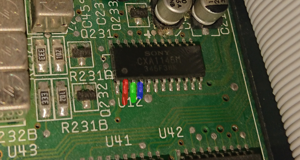
CXA1145
The last component for the color generation is the RGB encoder, a standard Sony CXA1145P chip which mixes the three analog color values into a composite video signal. I measured a different voltage for blue than for red and green (for the same color value) but since the value at the transistor was already off, this chip does not seems to be the problem.
Game over?
At this point I thought that's it since I don't have the tools for SMD chip removal and replacement and repair was impossible for my limited tools and SMD skills. I thought that it is very unlikely that simple components like resistors and a transistor breaks while the more complicated ICs seem to be perfectly fine. And I was right. At a second thought I realized I was too much focused on the chips itself so I turned to the actual connections between the chips.
Traces
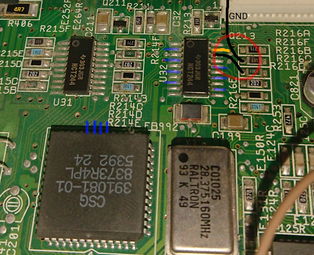
First I found the GND connection for resistor R216F (330 Ohm) is not actually grounded but I measured some voltage. I tested pulling the pin down to ground to see if that makes any difference but it didn't changed much. Then I checked the other resistors. First with the logic analyzer all 4 color resistors (1k, 2k, 4k, 8k) looked fine but using the oscilloscope I saw that the signal on the 1k resistor (R216B) was not actually that clean as on the output of the driver chip.
So it turned out that the motherboard trace between the output pin and the 1k resistor is partially broken. The same goes for the GND connection for the 330 Ohm resistor which should be connected to pin 19 of U32. I took some small wires and soldered them onto the board to bridge the connections. I connected the 330 Ohm resistor to the next easily available GND and I connected the 1k resistor directly to the driver pin 18.
Conclusion
That fixed the color issues all together. In hindsight the behavior of apparently self-healing after some minutes of using can be explained by broken traces as increasing temperature can temporarily "fix" or at least improve connection again. I hope the trace issues don't get worse over time but at the moment the picture is fine again.
So what are the findings:
- Start from the beginning to the end and check the signal values. You don't need expensive equipment if your measure carefully. A multimeter can be enough, a cheap logic analyzer helps a lot, and an expensive ocsilloscope is really helpful but not necessary.
- Have full control about the signals. For graphic output, modify each color channel individually. Use the background color as it also covers the border. Use as little other pixels as possible since they will alter the signal. Best case is a single color value for every pixel on the screen including the border.
- Check the input and output pins of all involved component.
- Check the actual traces between components. Don't assume that any connection, even GND, is actually what it is supposed to be.
Broken traces are pretty much impossible to fix on the motherboard itself, but luckily most of the time you can just bridge the connection using a wire. That does not look nice but usually it works fine, especially for digital signals on low distance.